Keywords: Levelling, reduction of levels, rise and fall methods, height of instrument
In the previous posts we have learned about the leveling, its principles and methods. Now we can move on to a practical illustration of this leveling process.
A level filed book or a level book is used for booking and reducing the levels of various points in a systematic way. There are two methods for reducing the levels namely
- The height of the instrument method
- The rise and fall method
Accordingly there are two types of level books. Both the methods are described below:
1. Height of the instrument method or height of collimation method (H.I method)
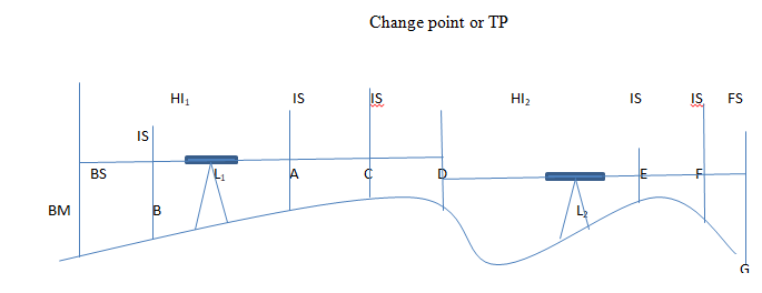
Below is a page of a level book for the height of the instrument method. There are seven columns. The first column indicates the station at which the staff is placed. The second column is for backsight (B.S). In the third column, the staff readings on intermediate stations are shown.

Figure 1: Differential leveling using HI method
As the instrument is shifted after taking reading on the staff at D, the reading is a foresight (F.S). This is entered in column 4. The staff is maintained at D when the instrument is shifted to the new position of the level (L2). The reading on the staff held at D after shifting the instrument to L2 is entered as a Backsight for station D. The new HI is written in the column 5. Thus, it can be seen that for a turning point like D, both FS and BS are entered whereas for other stations only one reading is entered.
| Column 1 | Column2 | Column 3 | Column 4 | Column 5 | Column 6 | Column 7 |
| Station | BS | IS | FS | HI | RL | Remarks |
The height of the instrument for the different positions of the instrument and the reduced levels of the points at which staff readings were taken can thus be obtained.
Arithmetic check
The calculations made in the computation of the height of the instrument (HI) and the reduced levels (R.L) can be checked by applying the following checks.
ΣBS – ΣFS = LRL-FRL
This is explained in the below problem.
Note: If ΣBS is greater than ΣFS, then the last point is higher than the first point. The above check is valid only for the arithmetic calculations and not on the fieldwork. Also in thus check, the errors in the calculation of RL of the intermediate stations could not be detected.
The height of the instrument method is illustrated through a problem as follows:
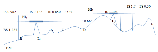
Example 1: Refer Figure 2 for the sketch showing the fieldwork in which the differential leveling has been done. The process of finding out the reduced levels of all the points (A, B, C, D, E, F and G) is explained below:

Figure 2: Levelling Example
The instrument is set up at position L1 and the preliminary adjustments are done. At first, the reading is taken on a staff held on the BM. This reading(1.285) is added to the RL of the BM (100.00) to get the RL of the line of sight or height of the instrument (HI) which is 101.285. Then the readings are taken on the staff held at A (0.422), B (0.982) and C (0.650). These readings when subtracted from the HI give the RL of A (100.863), B (100.303) and C (100.635). The last RL is calculated by the above method (100.960). Since the staffs held at E and F are not visible from the first instrument setup, the instruments is shifted to the new position L2. From the new setup, a staff reading is taken on D (0.884). Here, the station D is the change point (CP). The new HI (101.844) can be obtained by adding this reading to the RL of D. The RL’s of E, F and G (101.051, 100.144, and 101.344) are got by subtracting the corresponding staff readings (1.793, 1.700, and 0.500) from the HI.
| Station | B.S | I.S | F.S | H.I | R.L | Remarks |
| BM | 1.285 | 101.285 | 100.00 | BM at car shed floor | ||
| A | 0.422 | 100.863 | Parapet of well | |||
| B | 0.982 | 100.303 | Plinth of the building | |||
| C | 0.650 | 100.635 | ||||
| D | 0.884 | 0.325 | 101.844 | 100.960 | ||
| E | 1.793 | 100.051 | ||||
| F | 1.700 | 100.144 | ||||
| G | 0.500 | 101.344 | ||||
| SUM | 2.169 | 0.825 |
ΣBS-ΣFS = 1.344
LRL-FRL=101.344-100=1.344
Since ΣBS -ΣFS=LRL-FRL the arithmetic check is correct. However, this is not a check on the reduction of intermediate levels.
2. Rise and Fall method
Below table shows the page of a level book for the rise and fall method. There are eight columns. The first four columns are the same as in the first method. Instead of the column for HI, there are two columns (5 and 6) marked as Rise and Fall respectively. The last two columns are identical to that in the method one.
| Column1 | Column 2 | Column 3 | Column 4 | Column 5 | Column 6 | Column 7 | Column 8 |
| Station | BS | IS | FS | Rise | Fall | RL | Remarks |
Entries in the first four columns are the same as in the method one. The entries in column 5 and column 6 are made after computing the rise and fall.
Two consecutive readings from the same instrument positiongive the difference of levels between the points. If the 2nd point is lower, there is a fall or otherwise there is a rise. Thus the rise or fall of each point with respect to the immediately preceding station can be determined and entered in the field book.
The same problem can be done using the rise and fall method as follows:
| Station | BS | IS | FS | Rise | Fall | R.L | Remarks |
| BM | 1.285 | 100.00 | BM at car shed floor | ||||
| A | 0.442 | 0.863 | 100.863 | Parapet of well | |||
| B | 0.982 | 0.560 | 100.303 | Plinth of the building | |||
| C | 0.650 | 0.332 | 100.635 | ||||
| D | 0.884 | 0.325 | 0.325 | 100.960 | |||
| E | 1.793 | 0.909 | 100.051 | ||||
| F | 1.700 | 0.093 | 100.144 | ||||
| G | 0.500 | 1.200 | 101.344 | ||||
| SUM | 2.169 | 0.825 | 2.813 | 1.463 |
If ΣBS-ΣFS =LRL-FRL, the arithmetic work is correct
ΣBS-ΣFS =1.344
LRL-FRL=101.344-100=1.344
These calculations do not check the reduction of intermediate levels.
For station A, it is a rise with respect to the Benchmark.
Rise=BS on Benchmark-reading on station
A=1.285-0.422=0.863
For station B, it is a fall with respect to station A
Fall=IS on station A- IS on station B= 0.982-0.422=0.560
For station C, it is a fall with respect to station B
For station D, it is afall with respect to station C
For station E, it is fall with respect to station D
For station F, it is a fall with respect to station E
For station G, it is a fall with respect to station F
The values are entered in the appropriate columns in the table.
The RL of the various stations are calculated by adding the rise to the RL of the preceding station or by subtracting the fall from the RL of the preceding station
Comparison of Height of the Instrument method with Rise and Fall Method
The two methods of reducing the levels are compared in the table below:
| Height of the Instrument method | Rise and Fall method |
| The method is more rapid and saves considerable time and labor | The method is laborious as the staff reading of each station is compared, to get the rise and fall at each point. |
| It is well adapted for reduction of levels for construction works such as longitudinal works such as longitudinal or cross-section leveling operations | This method is most suited for determining the difference in levels of two points whenever accuracy or precision is required. |
| There is no check on reductions of reduced levels of intermediate stations | There is a complete check on the reduction of reduced levels of intermediate stations. |
| There are only two arithmetical checks, i.e., the difference between the sum of BS’s and the sum of the FS’s must equal the difference in the RL of the last and first station. | There are three arithmetical checks i.e., the difference between the sum of the BS’s and the sum of the FS’s must be equal to the difference between the sum of the rises and the sum of the falls as it must also be equal to the difference in RL’s of the last station and the first station. |
| Errors in the intermediate sights could not be detected using this method | Errors, in intermediate as these are used for finding out the rises or falls. |
from Civil Engineering Portal https://ift.tt/3hM1ESn


